Inhaltsverzeichnis
4. Working with CAD applications
4.1. Working with NX
4.1.1 Create and save parts
When creating a new item with UGMaster, proceed as follows:
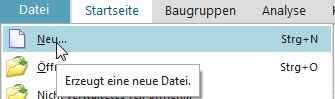
file → New… (CTRL+N)

- The creation of a new item as master part is visible as relationship “master” and contains the model.
- The creation of a new non-master part is visible as relationship “specification and contains the DrawingPart.
Selection of the seed part FFG_NX120_mag_model and filling of the mandatory attributes
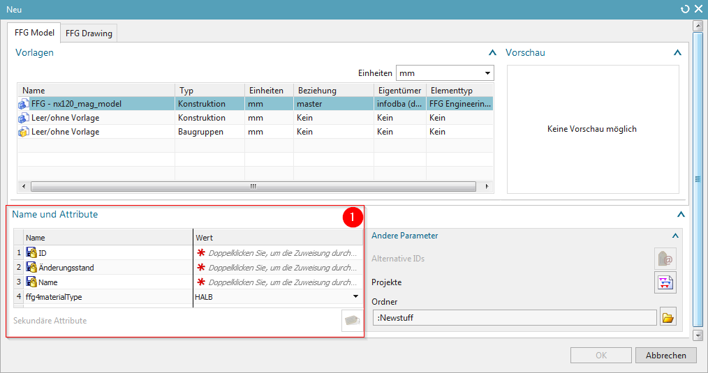
| 1 | Here certain mandatory attributes must be assigned to the newly created item. |
There are three procedures to open a UGMaster or UGPart existing in Teamcenter:
1. way:
Select the desired dataset directly in Teamcenter and open it via the NX icon  } in the toolbar.
2. way:
 | Double-click on the desired dataset (UGMaster or UGPart) in Teamcenter under the Revision item. |
Info:
If you have already opened NX and are using a feature there at this moment, an error message is displayed in Teamcenter. Close the feature in NX and then try again.
3. way:
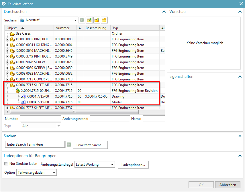
If you have already opened NX, you can open a dataset from Teamcenter via File → Open. When you select the item, the UGMaster is always loaded - if you want to load the corresponding UGPart, you have to select it explicitly. In the Open dialog, you can open both the Simple Search and the Advanced Search. These search functions will be discussed in the rest of this training document.
| | Double-click on the item, item revision or the corresponding dataset to open it in NX - alternatively you can confirm this with OK or open it with the right mouse button. | |
4.1.3 Revision of parts and "Save as"
- The revision of Item revisions and Save as is done with:
File menu → Save → Save as… - Create as new change state (revision)
- Save as new element creates a new part under a new part number
- Save as Alt-Rep creates a new dataset with alt. Geometry presentation under the current part / revision master.

| 1 | Action “Save as” - New element / New change status |
| 2 | A double click assigns a new change state number to the item revision. |
- If an item revision contains dependent files in addition to the Master part, the documents to be transferred can be selected, provided this is defined in the preferences.
4.1.4 Teamcenter Navigator
- The Teamcenter Navigator shows the current folder structure of the user
- The columns can be adjusted as required

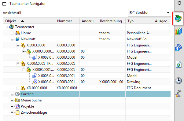
 | When you click on an item, item revision or dataset with the RMT, the following file operations are available: |
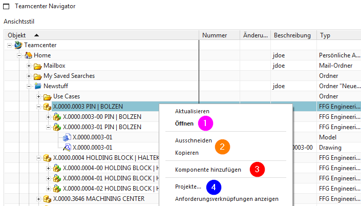
| 1 | Open a part file.. |
| 2 | Cut and Copy has the same effect as in the “My Teamcenter” environment |
| 3 | Opens the “Add Component” dialog |
| 4 | Adds the object to a project |
4.1.5 Teamcenter-Navigator Suche

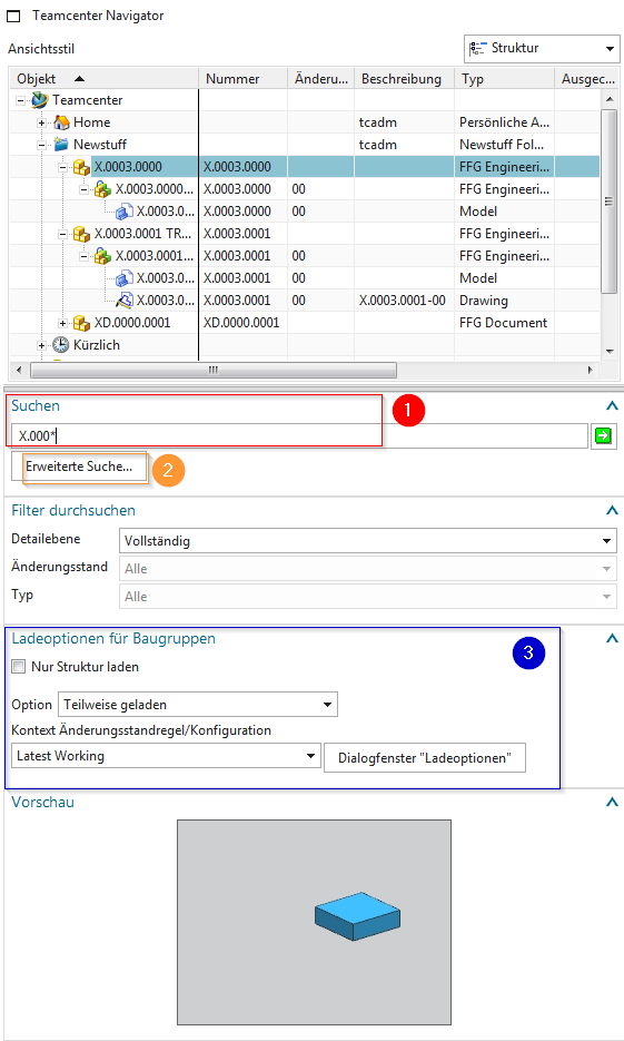
| 1 | Search with wildcards like in the Teamcenter environment |
| 2 | Advanced search |
| 3 | Loading options for assemblies |
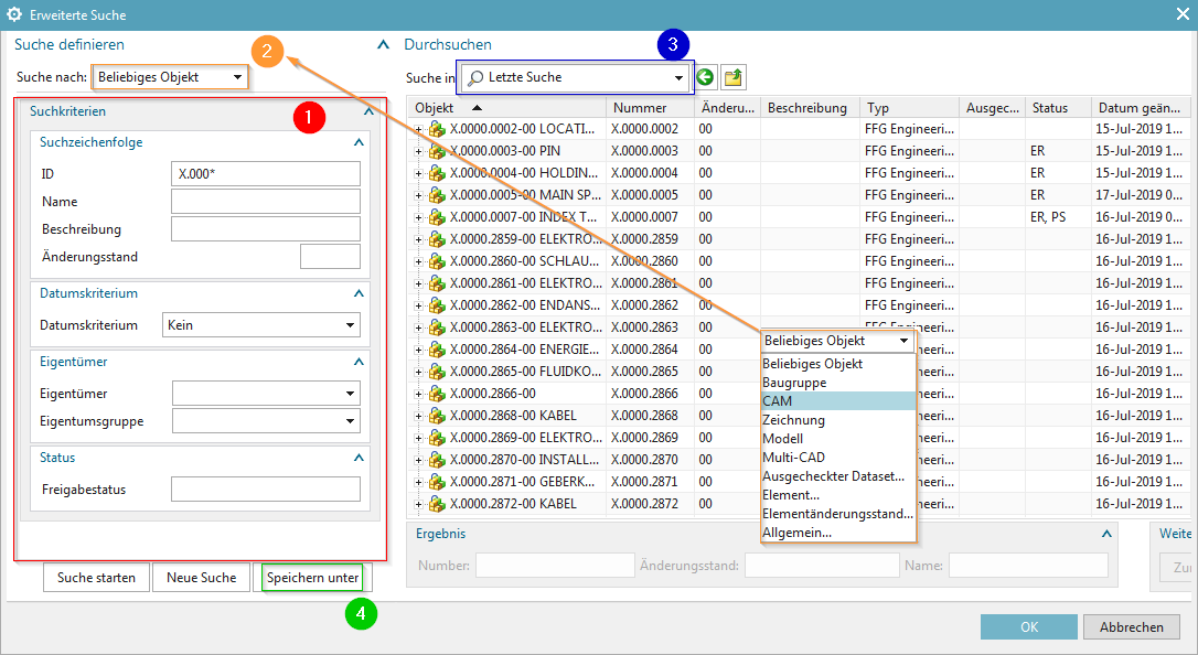
4.1.6 Teamcenter Navigator Advanced Search

| 1 | Search criteria |
| 2 | Search for: |
| 3 | Display last search |
| 4 | …searches saved in “My Teamcenter” |
4.1.7 Teamcenter function in the assembly navigator
- Keep all information from Teamcenter up-to-date
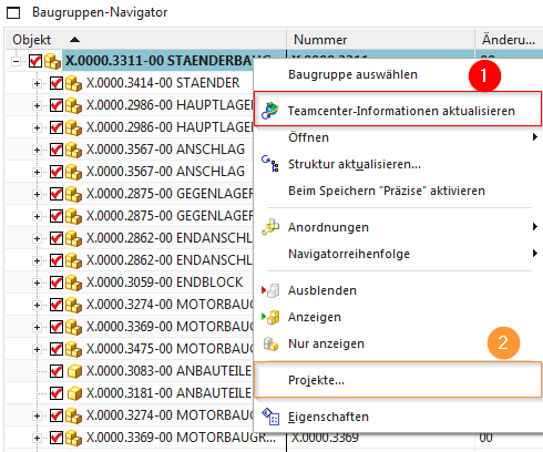
| 1 | Update information from Teamcenter |
| 2 | Adds the object to a project |
4.2. Exercises - working with NX
4.2.1 Exercise 1 - Creating an item from Teamcenter
Create a new part in Teamcenter as usual:
Select “File→New→Item “ and then select the type  .
.
Assign an item ID and assign a (provisional) name.
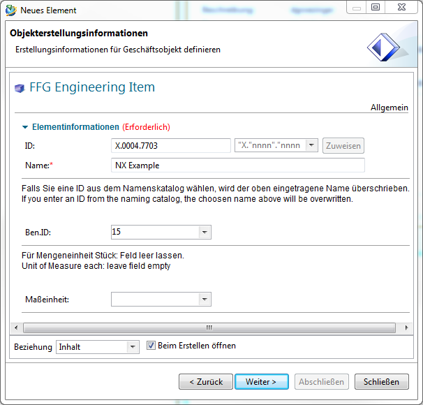
Select a name from the naming catalog.
Unit of measurement = Field empty (pieces)
Press “Next “
Enter the mandatory attributes relevant for a release.
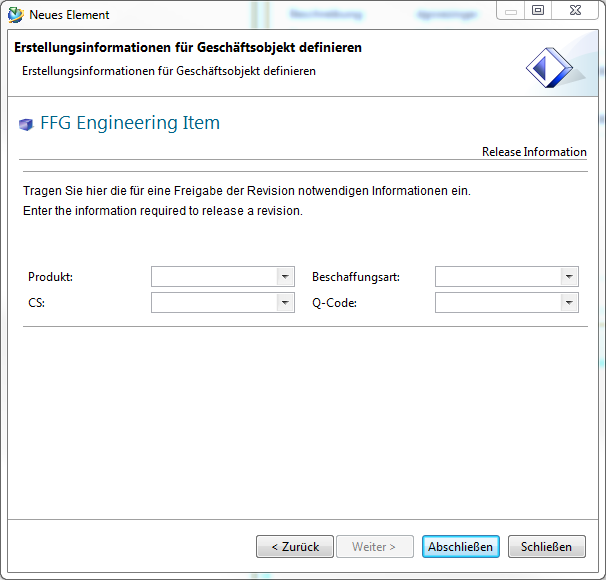
Press “Finish”.
Then select the newly created item or item revision and start NX via  in the menu bar. As soon as you save the part file in NX, the dataset (UGMaster) is created under the Revision item.
4.2.2 Exercise 2 - Create Items from NX
Before you start working in NX, please first load the role “FFG Standard” via the sidebar  .
.
- Creating a new item in Teamcenter is done in NX as follows:
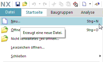
| 1. | Create a new record via File menu → New (Ctrl+N) |
- The creation of a new item as master part is visible as a relationship “master” and contains the model.
- The creation of a new non-master part is visible as relationship “specification” and contains the DrawingPart.

| Durch einen Doppelklick in die mit einem Stern markierten Felder werden zur Erstellung benötigte Pflichtattribute automatisch ausgefüllt. |
Exercise:
1. create a UGMaster with the corresponding item in NX, create a geometry and save it back to Teamcenter
2. check the structure of your created item in Teamcenter [Item, Item Revision, Dataset]
3. enter all metadata required for the approval in Teamcenter.
4.2.3 Exercise 3 - Creating a drawing
To create a drawing, you have to create a reference object to your existing UGMaster in Teamcenter - this is called UGPart.
To create a UGPart, you must proceed as follows
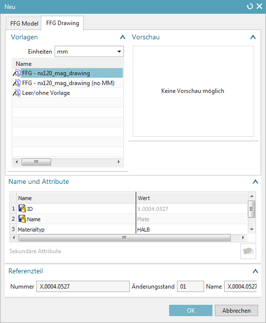
File menu → New (Ctrl+N)
Then select the “FFG Drawing” tab and the corresponding seedpart “FFG-nx120_mag_drawing “. The associated attributes are taken over by the Revision item. Confirm this with OK.
Exercise:
1. create a UPart in NX, place your desired views and detail them
2. check the structure of your created item in Teamcenter [Item, Item Revision, Dataset]
3. release the Item Revision you have created! [Engineering Release]
4. PDF, JT and TIFF should be created as neutral formats.
5. check the structure of your created item in Teamcenter [Item, Item Revision, Dataset]
4.2.4 Exercise 4 - Revise and save parts
- The revision of master parts is done with: File menu → Save → Save as…
- Create as new change status (revision)
- Save as new element creates a new part under a new part number
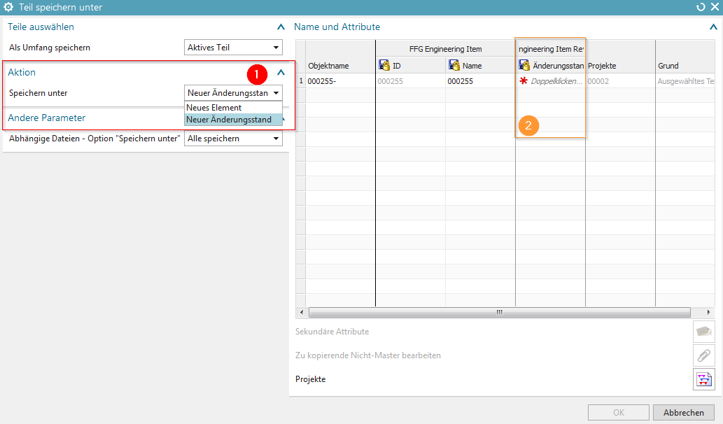
| 1. | Action “Save as” - New element / New change status |
| 2. | A double click will assign a new revision number to the Revision item. |
- If an item revision contains dependent files in addition to the Master part, the documents to be transferred can be selected if this is defined in the preferences.
Exercise:
1. create a “new change status” of your released item in NX
2. check the structure of your revised item in Teamcenter [Item, Item Revision, Dataset]
3. execute “Save as
4. check the structure of your revised item in Teamcenter [Item, Item Revision, Dataset].
4.2.5 Exercise 5 - Navigating in Teamcenter Navigator
- The Teamcenter Navigator shows the current folder structure of the user
- The columns can be adjusted as required
| | When you click on an item, item revision or dataset with the RMT, the following file operations are available: |
| 1 | Open a part file. |
| 2 | Cut and Copy has the same effect as in the “My Teamcenter” environment. |
| 3 | Opens the “Add component” dialog |
| 4 | Adds the object to a project |
4.2.6 Exercise 6 - Searching for objects in Teamcenter
| 1. | Search with wildcards like in the Teamcenter environment |
| 2. | Advanced search |
| 3. | Loading options for modules |
4.2.7 Exercise 7 - Advanced Search of Objects in Teamcenter
| 1. | Search criteria |
| 2. | Search for: |
| 3. | Display last search |
| 4. | …searches saved in “My Teamcenter” |
Exercise:
1. create a new item.
2. use the different search methods to find the components of your seat neighbour and of you.
3. insert the components into the UGMaster you have created
4. check the structure of your created item and the created structure via the Structure Manager in Teamcenter. [Item, Item Revision, Dataset].
4.2.8 Exercise 8 - Teamcenter functions in the Assembly Navigator

| 1. | Update information from Teamcenter |
| 2. | Adds the object to a project |
Exercise:
1. open the assembly you have created
2. use the Structure Manager to change a component to GEOMETRY = NO.
3. check the structure setup in NX - then update the properties and the structure - then check it again
4. select a component in NX and set the component as “reference” via the properties
5. select a component in NX and set the component as “non-geometric” in the properties
6. check the structure using the Structure Manager in Teamcenter
4.2.10 Exercise 10 - NX Tools - Loading the Drawing Frame
When adding the drawing frame and sheet format, proceed as follows:
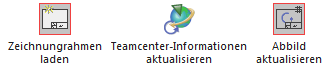
| 1. | Overview - Frame functions |
 |
|
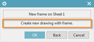
| 2. | Load drawing frame |
 |
|
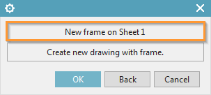
| 3. | Drawing frame on sheet 1 |
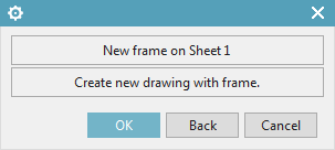 |
|
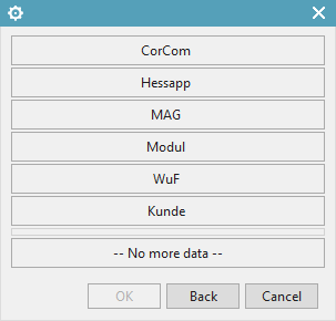
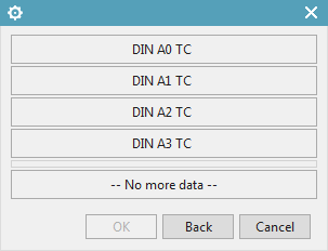
| 4. | Select the desired frame |
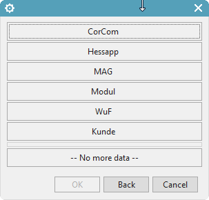 |
|
| 5. | Selecting the drawing format |
 |
Info:
In order to display all attribute values in the drawing frame, the UGPart must be saved to Teamcenter and the drawing header must be updated with the “Update Image” function.
Exercise:
1. open the UGPart of the item revision that you have revised
2. insert a drawing frame
3. update the drawing header - check the drawing header
4. save the UGPart to Teamcenter
5. update the drawing header - check the drawing header
4.2.11 Exercise 11 - NX Tools - Creating a Drawing Sheet
| 1. | Overview - Frame functions |
 |
|
| 2. | Load drawing frame |
 |
|
| 3. | Drawing frame on sheet 1 |
 |
|
| 4. | Select the desired frame |
 |
|
| 5. | Selecting the drawing format |
 |
|
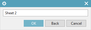
| 6. | Accept naming of sheet n |
 |
Aufgabe:
1. create two new drawing sheets with different drawing frames
2. change attributes in Teamcenter and check the properties in NX before updating
3. update the attributes.
4.2.12 Exercise 12 - NX Tools - Change drawing frame / format on existing drawing
| 1. | Overview - Frame functions |
 |
|
| 2. | Load drawing frame |
 |
|
| 3. | Drawing frame on Sheet 1 |
 |
|
| 4. | Select the desired frame |
 |
|
| 5. | Selecting the drawing format |
 |
|
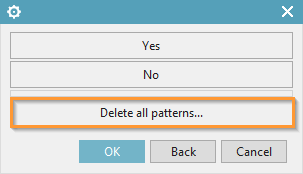
| 6. | Delete all Patterns |
 |
Exercise:
1. change the drawing frame on each drawing sheet so that the individual sheets have different drawing frames
2. save the UGPart
3. release the Revision 01 item [Release after “ER”]
4. create the neutral formats JT, PDF and TIFF
4.2.13 Exercise 13 - NX Tools - Other important functions
 | Transfer of metadata from Teamcenter to NX |
 | Manual update of metadata in the title block |
Exercise:
1. check out the Revision item in Teamcenter.
2. for example, change the naming and additional naming.
3. check the Revision item into Teamcenter
4. update the Teamcenter information
5. update the title block.
4.3 Working with AutoCAD
4.2.1 Introduction
In this project a simple interface from Teamcenter to AutoCAD was implemented. With this interface AutoCAD files can be opened and edited from Teamcenter and the changes can be saved in Teamcenter again. All PDM functions like search, release etc. are also possible analogous to all other part types (2D/3D design with NX).
It is not possible to create a DWG dataset from Teamcenter. It must be created locally using a corresponding template and then attached to the Revision item by drag & drop. The same can be done with existing AutoCAD drawings, which are located locally or on network drives.
4.2.2 Create item
It is not possible to create an AutoCAD file (or a part with an AutoCAD file) directly from AutoCAD in Teamcenter. The following procedure is available for this:
Create a new part in Teamcenter as usual:
Select “File → New → Item “ and then select the type  .
.
Assign a Item ID and assign a (provisional) name.
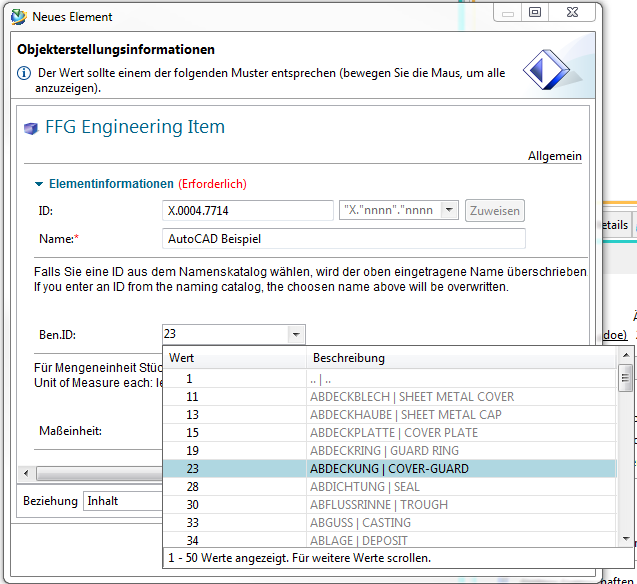
Select a name from the naming catalog.
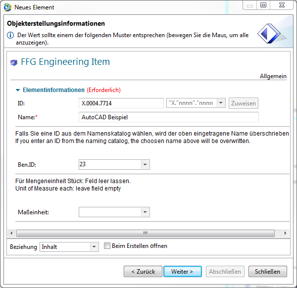
Press “Next”.
Enter the essential master data.
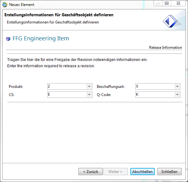
Press “Finish”.
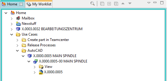
4.2.3 Insert dataset in Item Revision
Now take an AutoCAD file located on a network run or locally or create a new file with AutoCAD and drag and drop it via Drag and Drop onto the newly created revision in Teamcenter.
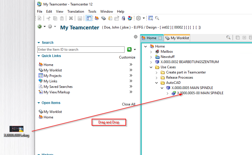
The following dialog appears. The dataset name is taken over by the Revision item when you perform the next step.
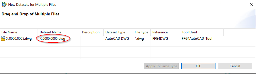
Then press “OK”. The file is now attached to the revision as so-called “Dataset” and is thus available in the PLM system.
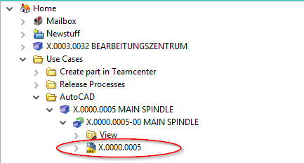
4.2.4 Open drawings in Teamcenter
To edit the AutoCAD file further, double-click on the dataset. AutoCAD is opened and the file is loaded.
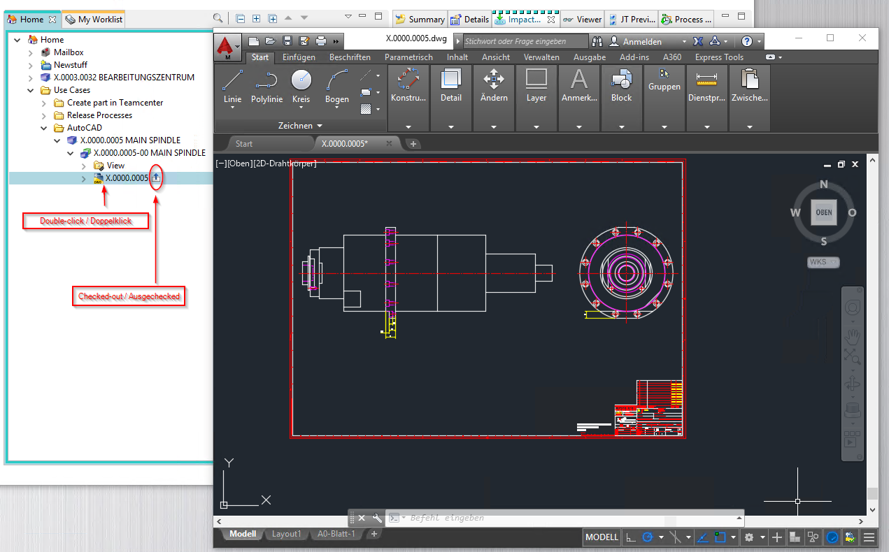
Info:
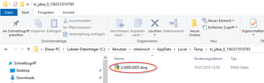
The file is checked out to a local directory in your computer's temporary folder when opened. All changes are saved there as long as the AutoCAD program remains open.
If necessary, make sure that a “Checked-Out “ symbol is displayed on the dataset.
4.2.5 Save drawings in Teamcenter
After finishing the work, save the file and close AutoCAD. The file is checked in to Teamcenter and the “Checked-Out” symbol disappears. This process may take some time because the file is uploaded to the volume server in the background.
Exercise:
1. Create an item.
2. attach a DWG to the Revision item.
3. open the dataset in AutoCAD
4. make a change in AutoCAD and save it back
5. close it and open the dataset again.
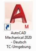
4.2.6 AutoCAD-Integration
An AutoCAD environment was specially configured for the Teamcenter integration. You can start this environment manually by clicking on the following icon on your desktop - or by double-clicking on the AutoCAD dataset in Teamcenter.
4.2.6.1 Creating an AutoCAD drawing
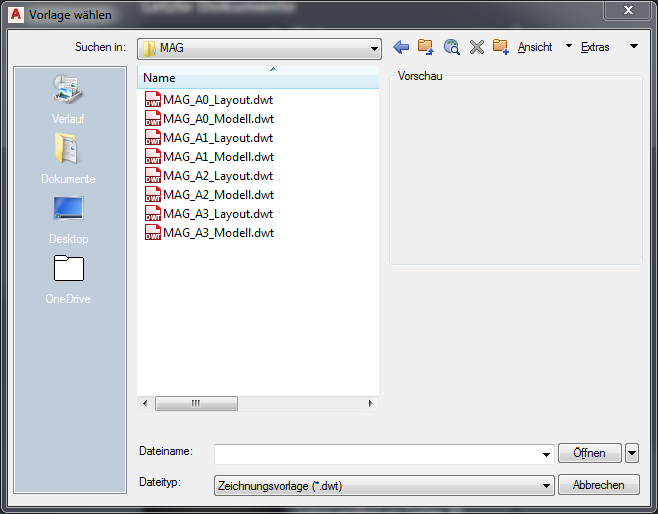
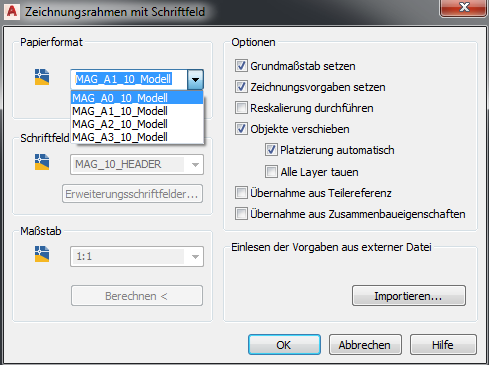
A new AutoCAD drawing is created via the menu “File” –> “New”.
Here you are offered 3 template directories:
- MAG frame
- Customer frame
- Templates (standard templates)

Now navigate to the desired directory and select the appropriate template:
| Type | Description |
| Model | Drawing frame is in the model space |
| Layout | Drawing frame is in the layout area |
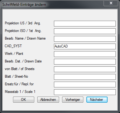
4.2.6.2 Editing the attributes in the title block
Once you have created the drawing frame, for example in the model space, you can fill the metadata by double-clicking on the drawing header.
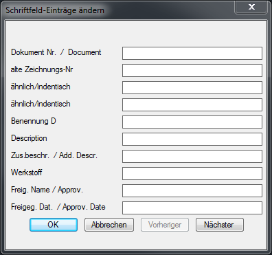
This dialog can consist of several dialog pages - these can be controlled via “Previous” or “Next”.
4.2.6.3 Change drawing frame and format
If a drawing already exists, you can change the drawing frame as follows
1. First, navigate to the Lettering menu and select the Font frame function.
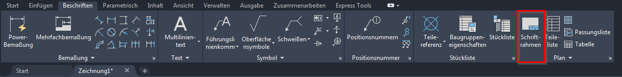
2. In the “Edit frame / title block” function, select the options “Change frame / title block “ and the corresponding function “Change drawing frame “.

3. Select the desired new format and confirm with OK.
4.2.6.4 Adjusting the page layout
In order to be able to adjust the page layout, you must start the page setup manager. You must proceed as follows:

| | Using the RMT on the Layout tab, you can access the page setup manager. |
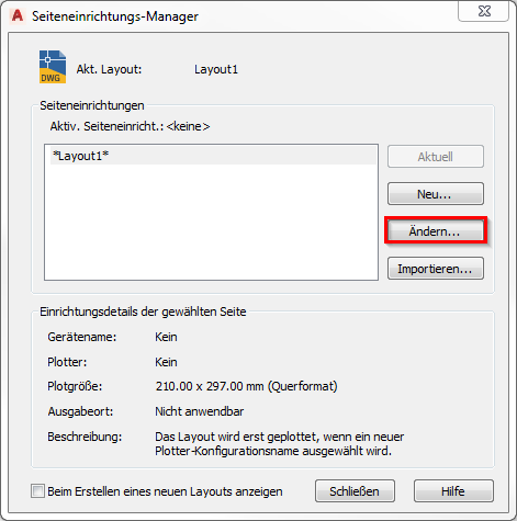
Now select the “Change” function - the following dialog will open:
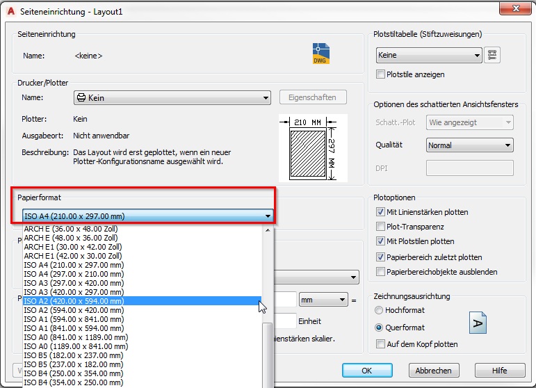
Select the desired format and confirm with OK.
4.2.6.4 Add further layouts
You can add more layouts in AutoCAD by doing the following.
1. add another layout as shown in the following figure.
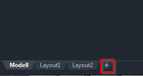
2. Then select the desired format and drawing frame.
3. after you have added the drawing frame, adjust the layout and the plotting distance (must be zero) accordingly

You also set the coordinates of the frame to X=0 Y=0.
4. fill the attributes of the title block with values